8 Results
View results:
Sort by:
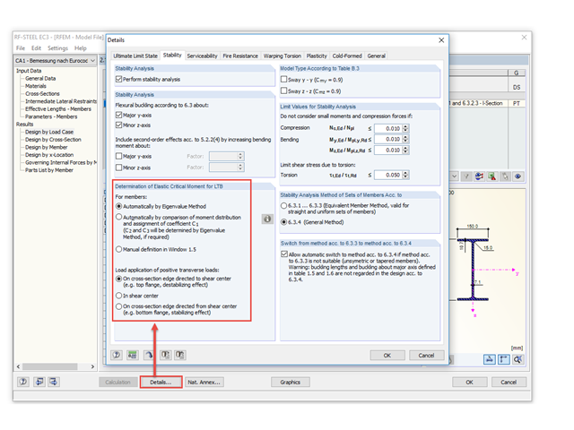
Occasionally, the question arises how to determine the correct load application point of the positive transverse loads in RF-/STEEL EC3 and RF-/STEEL AISC.

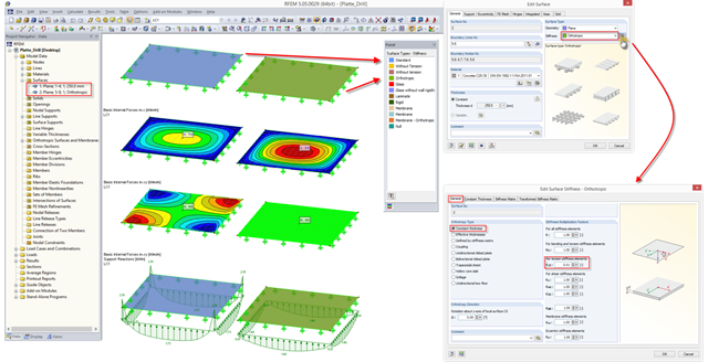
You can color the surfaces in the direction of the local z‑axis using the indicated option in the Display Navigator. By default, the side lying in the negative z-direction is colored red and the side lying in the positive z-direction is colored blue.
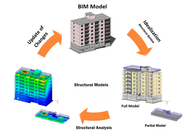
Building Information Modeling describes what is possibly one of the most important current topics in the entire construction software industry. However, the process is not that new, and it is a well-known fact that the total costs of a project can be positively influenced by good planning in the initial stage.
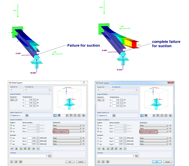
If nodal supports should have an effect in certain directions only, you can define failure. Here is an example of a single‑span beam, of which the right support can only absorb positive vertical loads. The load comprise vertical suction load and horizontal load. However, there are 2 failure options:
1) Failure if negative PZ'
2) Failure all if negative PZ'
The difference is illustrated in the graphic.
1) Failure if negative PZ'
2) Failure all if negative PZ'
The difference is illustrated in the graphic.
In a plate with full torsional stiffness, a significant part of the loads is transferred by torsional moments. If it is impossible to set the positive effect of this additional stiffness in the calculation (for example, due to a butt joint of a precast plate in the stiffness area), you have to reduce the torsional stiffness.
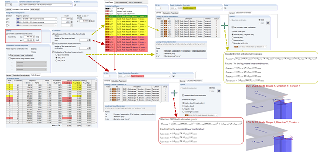
When accidental torsion is considered in the RF-/DYNAM Pro - Equivalent Loads module, the module exports two load cases for each eigenvalue: one with positive torsional moment, the other with negative torsional moment. The generated equivalent loads themselves do not differ in these two load cases.
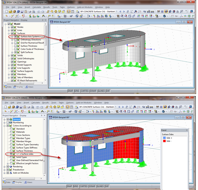
When calculating the surface reinforcement in RF-CONCRETE Surfaces, the result values for both surface sides +/- z are available. If you are unsure which side of a surface is the positive or the negative z side, you can hide the local coordinate system of each surface in the RFEM Project Navigator - Display under "Model" → "Surfaces" → "Surface Axis Systems x,y,z". In the case of complex structures, this can quickly become confusing. Displaying multiple axis systems makes it difficult to recognize the incorrect direction of a surface, for example (see the figure on the top).
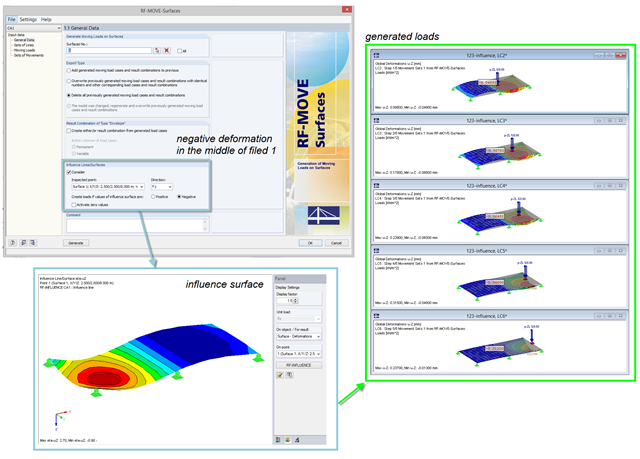
For the reduction of loads generated in RF‑MOVE Surfaces, you can consider the influence surfaces of a selected point. The influence surfaces are determined by RF-INFLUENCE. This procedure is useful in cases where only unfavorably acting loads should be considered. Depending on the unfavorable action, you should select the positive or negative direction.